How to overclock your Block Erupter And possibly destroy it in the process.
Caution do this at your own risk. I blew mine out so you don’t have to!
That said. Here is how I got my block erupter overclocked to 56o MHz briefly before it died.
Lets start off first with a simple overview of the board
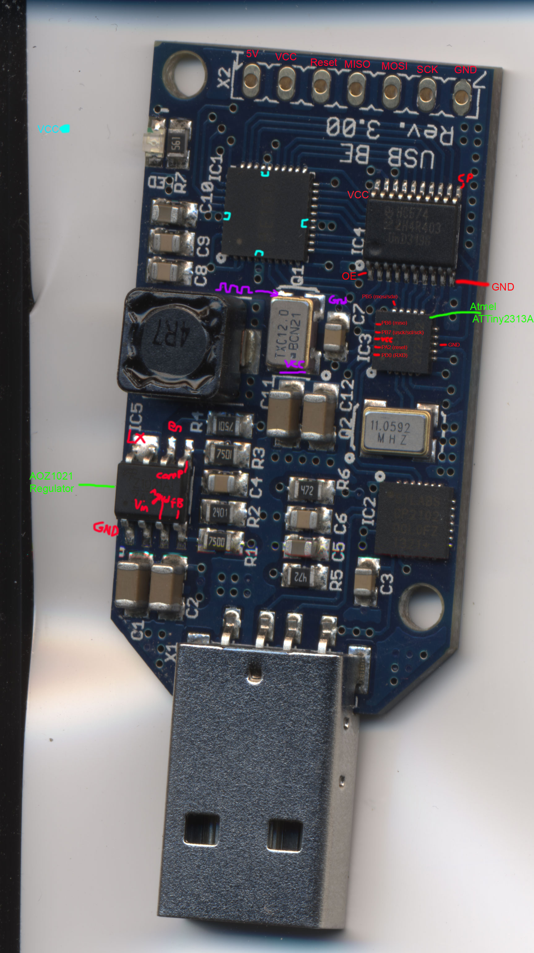
Click for larger size

The heart and soul of your Block Erupter. Please note: putting a heat sink on top of this chip will have little if any effect as the heat side of the chip is soldered to the board. You are better off with changing the stock heat sink on the back of the board, or adding on to it as I will show you later. The 4 large 2 pin wide traces are all the main + voltage to the asic.

To maximize heat transfer I suggest you carefully remove the solder mask on the back of the board where the asic lies on the other side. I did this with a dull Exacto knife and very little pressure slowly scraping across the surface. If you go this route: USE A NON CONDUCTING THERMAL GREASE!!! or Heat transfer pad!!!! Artic silver may short things out and leave you with a mess to clean up, if not a dead board.

This is a Atmel attyiny2313a. This contains the firmware that bridges the usb – serial adapter chip to the asic. You would be stupid to put a heat sink on this as it will never get warm. If it does your doing something wrong. I have seen sales on ebay of heat sink kits for the block erupter that put a heat sink on this chip

(Moogle Face Palms)
Next we have the Silicon Labs Uart – usb adapter.
Not only does it do the proper conversion, It coverts the 5v usb to 3.3 that powers the AVR chip

Again you would be stupid to put a heat sink on this.
Moving along we get to the fun parts :) This is where your soldering skills will take place.

Behold the asic voltage regulator and all its glory. You will learn to hate this chip :D as it will be the source of many of your hardware error issues. Here is the datasheet, become familiar with it as you will need to know how to properly modify the core asic voltage.
Next we get to the clock generator

This operates at 3.3v and 12 MHz. Please note the 3.3v is very important here, as this may be the thing that ended up frying my asic.
The core asic clock speed is this crystal times 28. So 12 MHz * 28 = 336 MHz.
Here is a list of oscillators on Digikey you can experiment with if you dare.
http://goo.gl/nJeCVo< Long Digikey url so I shortened it

Lastly the resistors you will need to modify to change the core asic voltage. R1 is conveniently the same as R1 in the datasheet for the Regulator and the same applies to R2 :)
To get a higher voltage you can change R1. Do the math or be lazy like I did :D
Here is the setup I was using.

I used a 10K ohm pot to adjust the core voltage with a volt meter on the pin I soldered to the main asic core voltage line. You should be very careful if you use my method and always have a volt meter on the asic core voltage line. I mostly did changes with the Block Erupter connected to my bench power supply with the current limited to prevent any mishaps.
To the left and right of the Block Erupter are my 2 different clock gen circuits I used. I used a simple machine pin style female header so I could easily swap out the crystal. I found 2 different schematics on Google images.

Closer view of the board. Simple 74f04 clock source circuit.

The other board. This one gave me more trouble and wasn’t too stable.
 Closer view of my modifications. I put a capacitor on the main usb voltage lines to filter out any noise it might have picked up. Removed R1 and installed a 10k ohm trim pot. Voltage pin probe on the asic core voltage line to monitor with my volt meter. Trick is to set the trim pot to 1.2K ohms before you solder it in place then you can just make slight adjustments to home in a stable voltage. I then removed the clock gen and put it on its side. This way I could just solder a small wire to it to get the default clock back to test if I did any damage at any time. I also soldered in a pin that I could connect my oscillator circuits to.
Lastly I added a mini heat sinked 5v fan to the back held on with thermal grease and a few small dabs of hot glue on the sides.
Results & Things Learned:
- I ended up destroying my Block Erupter in the end. I pushed it too far and too hard using a 20 MHz crystal, that is 560 MHz. but this lasted 5 minutes tops before the asic became non responsive.
- If you screw up the clock gen to the asic or have noise on your signal then the Block Erupter will identify its self as 000000 or some random number sequence then what it should be.
- A 14 MHz crystal is stable. 16mhz is pushing it
- The Block Erupter Asic may not like a 5 clock source too much.
- The lowest crystal speed that I was able to use without changing the voltage was 13.5 MHz. There wasn’t much of a speed increase but you will get some satisfaction in getting a higher hash rate and more accepted work in your mining pool. All though with out changing the voltage resistors you may get more mining hardware errors ad the asic wants to have more voltage.
Lots of people have been wanting to give me bitcoins for my hard work :)
So if you feel generous send them here : 1A7FReBCeFXJR8VUhX4rCm8v5C5mExakHJ
Thank you and be safe.
Watching for updates!
Thanks!!
Can you just swap to a 14 or 16 mhz crystal and not change anything else and get improved results?
The lowest crystal speed that I was able to use without changing the voltage was 13.5 mhz. Wasn’t much of a speed increase but was noticeable. Though with out changing the voltage resistors you may get more mining hardware errors.
Pingback: rndm(mod) » Overclocking your Bitcoin miner
Pingback: Overclocking your Bitcoin miner - RaspberryPiBoards
Pingback: Overclocking your Bitcoin miner | Blog of MPRosa
Pingback: Overclocking your Bitcoin miner | Daily IT News on IT BlogIT Blog
Perhaps you could cool it by immersing the circuit into mineral oil: http://www.tomshardware.com/reviews/strip-fans,1203.html
Pingback: Overclocking your Bitcoin miner | bitcoinfornewbies
Ahaa, its fastidious conversation regarding this post here at this website, I have read all that, so now me also commenting at this place.
What resistors do I have to buy and where exactly do I put them to increase the voltage?
Awesome. Now that they are down to $65 a piece on http://piminers.com it’s not so bad to fry one or two. 400MHz of hashing power is a nice 30% jump from the stock one.
Hi !
What do I have to change to get the 14.3MHz or 14.7MHz crystal oscillator running ?
greets Northwave
Pingback: It was only a matter of time: How to overclock your Block Erupter | Bitcoin Buzz – Bitcoin Forum Talk
Pingback: Virtual Mining Bitcoin » It was only a matter of time: How to overclock your Block Erupter
Pingback: It was only a matter of time: How to overclock your Block Erupter | NewsBitcoin.com
Thanks for the interesting walk through of the board components.
It’s good to see someone has finally debunked some of the misinformation regarding aftermarket heat sinks on some of the components.
Pingback: Overclocking the Block Erupter USB bitcoin miner « adafruit industries blog
Pingback: How to overclock your block erupter to 560mhz | Bitcoin Buzz – Bitcoin Forum Talk
A note on heat-sinking the ASIC: I glued some RAM heatsinks onto the upper surface of my Eruptors’ ASICs – and they get really hot pretty quick (no forced airflow back then). After a minute or two I measured some 50°C+ above ambient, which to me indicates that a lot of heat can be removed from the chip this way, and that heat-sinking (also) on this side is definitely not a bad idea.
They use a base of 2.5 W so how much more power did they use after the addition of the fan and the increase in voltage and current draw?
Did the MH/J stay constant or degrade? There’s a sweet spot where the efficiency of electricity use per MH earns the most profit.
great work!
too bad it’s broken.
can you show us a modification which is safe and stable?
Hi, I’ve done some things preparing for this hack: (ASIC heatsinks, huge common heatsink for 4 pieces, dirt cheap hub for 4 with beefy power…) and it’s working like a charm in Linux (bamt). I’m still under threshold with BTC mining, so You’ll have to take my word for a small donation…
Now the question[s]: Where should I settle (I don’t want to buy VCXOs) with frequency, between 14 and 16MHz, and could I feed one signal to all four ASICs (load/capacity wise)? I’m aiming to buy 7C/7W TXC or CPFS72/73 fixed freq. (16MHz is quite common)
Thanks in advance
Hi, I want to ask, if it is safe to overclock blockerupter to 16MHz (R1=1k5) with active cooling (heatsink with cooler from VGA). Does it decrease lifetime ? If yes, which freq. does not decrease lifetime ?
Thank You
What about IC4? This is a chip that many of the heat sink sets include, not IC3.
Brilliant! Especially liked the moogles face palms! :P
What a shame its broken! Better luck next time
Pingback: Overclocking your Bitcoin miner | Hackaday